

There’s a moment in product development where the mood changes. The concept has been approved. The visuals look sharp. Everyone is excited. Then the factory asks one simple question. “How are we making this?” If the answer is vague, the project gets expensive. This guide centers on design for manufacture to keep decisions practical and buildable.
This is the part many teams miss. Design for manufacture is not a late stage clean up. It’s a way of thinking that protects time, cost, and quality from day one. Factories do not care about your render. They care about draft, wall thickness, tool access, assembly order, yield, and how many minutes it takes to build one unit.
Once you start seeing projects through that lens, a lot of the noise falls away. You stop chasing polish. You start earning truth.
Quick navigation
Design for manufacture creates a clearer handover into manufacturing and launch.
- DFM is not a phase
- The cost of getting it wrong
- The big four pitfalls
- My DFM preflight checklist
- Tolerances, stackups, and why “it’ll be fine” is not a plan
- The assembly story, the hidden product
- Supplier reality, how to get better answers early
- Examples from my work
- How I help teams avoid DFM blowouts
Design For Manufacture: DFM is not a phase
Design for manufacture helps teams align design intent with engineering reality.
Most teams treat DFM like a checkpoint. Design first, then DFM, then tooling, then production. That sounds tidy. It also creates avoidable pain. In real projects, if you leave manufacturing thinking until “later”, later arrives with a list of changes. Some are small. Some rewrite the product. All of them cost time.
This is why I like to treat DFM as a running conversation, not a final gate. It starts the moment you define a shape and it never fully stops. It does not mean you design like an engineer. In practice, it means you design with engineering reality in the room. A useful proof point here is DFMA practice. Boothroyd Dewhurst have long argued that investing earlier can prevent late changes and reduce total design time, they have reported large time savings when DFMA is applied upfront. Source
That matches what I see in practice. Spend a little time early. Save a lot later.
The cost of getting it wrong
Design for manufacture keeps decisions grounded and reduces late-stage rework.
DFM mistakes rarely show up as one dramatic failure. They show up as death by a thousand cuts.
- Tooling changes because draft was forgotten
- Parting line changes because shutoffs were unrealistic
- Assembly time blows out because screws are hard to reach
- Scrap increases because a surface is too sensitive to variation
- Quality issues appear because tolerance stackup was never analysed
The most painful part is this. Once you are in tooling, you are no longer choosing the best solution. You are choosing the least bad compromise. So the real value of DFM is simple. It keeps your options open while change is still cheap.
This is also why I’m big on CAD and prototyping as decision engines, not cosmetic checkpoints. If you want that framing, these two posts connect tightly:
The big four pitfalls
Most DFM issues fall into four buckets. If you get these right early, you avoid most of the drama.
1) Geometry that cannot be made
This is the classic one. A part looks clean in CAD, but the tool cannot release it, or the part will warp, sink, or mark. Common culprits:
- No draft on vertical walls
- Undercuts with no plan for slides, lifters, or redesign
- Wall thickness that varies wildly
- Sharp internal corners that create stress and poor flow
- Bosses and ribs that are too thick, leading to sink and distortion
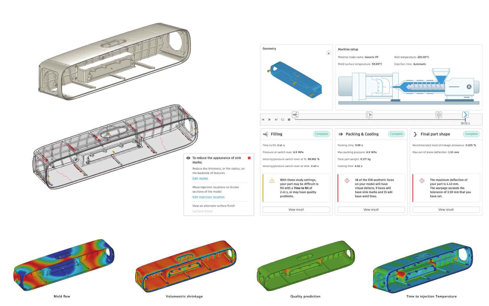
Injection moulding guidelines consistently push the same fundamentals, draft, uniform walls, radii, and careful undercut management. Source
2) Assembly that cannot be assembled
As a result, A product is not a collection of parts. It is a sequence. If your design requires a technician to bend time and space to reach a fastener, you have a problem. Common culprits:
- Fasteners with no tool access
- Snap fits that require too much force, or are sensitive to tolerance
- Cable paths that pinch during closure
- Seals that are impossible to install consistently
- Assemblies that need three hands
This is where the workshop mindset becomes real leverage. A rough prototype and a screwdriver will tell you more than a week of meetings. Related article
3) Tolerance and variation ignored
This is the quiet killer. Every process produces variation. If you design a product that only works when parts are perfect, you will pay for it, either in scrap, in rework, or in warranty. Common culprits:
- Stacking multiple tight tolerances without analysis
- Assuming moulded parts behave like machined parts
- Over specifying tolerances everywhere, driving cost for no benefit
- Relying on friction fits with no control of variation
Manufacturing partners publish typical tolerance expectations by process for a reason. It is a reality check. Source
4) Cost blowouts hiding inside complexity
Cost does not come from one big decision. It comes from accumulated complexity. Common culprits:
- Too many parts
- Too many finishing steps
- Tooling complexity driven by avoidable geometry
- Excessive fasteners and assembly time
- Materials that demand difficult processing
If you want one simple heuristic, reduce part count first. Part count is assembly time. Assembly time is money.
My DFM preflight checklist
Here’s what I use as a practical DFM preflight. It’s not meant to be exhaustive. It’s meant to prevent avoidable mistakes before steel gets cut.
Preflight A, manufacturing assumptions
- What is the process for each major part, injection moulding, CNC, sheet metal, die cast, soft goods, or something else?
- What is the expected production volume range?
- What is the target cost and the target assembly time?
- Which environmental conditions are expected: water, dust, UV, heat, and impact?
Preflight B, geometry fundamentals for moulded plastic
- Draft applied on all relevant faces, with extra draft for textured surfaces
- Walls reasonably uniform, transitions gradual
- Ribs and bosses sized to avoid sink, warpage, and weak points
- Internal corners radiused, external corners supported
- Undercuts identified, with a clear plan, remove, redesign, or tool for it
- Parting lines, gate locations, and ejector areas considered early
Specifically, If you want a concrete injection moulding reference point, Protolabs and Hubs publish clear guidance on draft and geometry rules of thumb, which aligns well with what factories will tell you in real life. Source
Preflight C, assembly story and tool access
- Assembly order written step by step
- Tool access checked, driver angles, clearance, reach
- Cable routing and strain relief validated
- Seals and gaskets have an installation plan
- Critical interfaces prototyped, not just modelled
Preflight D, tolerance strategy
- Critical interfaces identified, what actually needs precision
- Non-critical surfaces allowed to float, no over tolerance
- Stackups mapped for the main functional chains
- Process capability assumed realistically, based on process and supplier input
Preflight E, finish and quality reality
- Cosmetic surfaces identified, with a plan for parting lines and ejector marks
- Texture and draft aligned, texture needs more draft, always
- Finish strategy matches environment and wear expectations
- Quality criteria written down, gaps, flushness, surface, and cosmetic limits
That last point is underrated. If quality is not defined, the factory will define it for you.
Tolerances, stackups, and why “it’ll be fine” is not a plan
Let’s talk about tolerance stackups in plain language. Every part has variation. When you assemble multiple parts, those variations add up. Sometimes they cancel out. Sometimes they pile up in the same direction and you get interference, wobble, leakage, or rattles.
In practice, There are multiple ways engineers analyse stackups, worst case and statistical methods like RSS are common approaches. Autodesk and PTC both describe these methods in their tolerance analysis documentation. Source Source
A practical way to start
- Pick one critical function, sealing, alignment, button feel, latch engagement, connector mating.
- Identify the parts that create that function.
- Write the tolerance chain in one direction.
- Ask, what happens if each part drifts toward its limit?
Even a rough first pass makes your design smarter, because it tells you where to spend precision and where to relax it. This also connects to CAD thinking. Early CAD is where you expose these chains. Late CAD is where you suffer them. Related article
The assembly story, the hidden product
If you want a real shortcut in DFM, it’s this. Write the assembly story early. Not later. Not when the supplier asks. Early. Because assembly is where geometry becomes reality. It is where cables get pinched, seals get twisted, clips get snapped, and screws get stripped.
Here’s a simple assembly story template:
- Base structure and datum part
- Internal components installed, PCB, battery, speakers, motors, whatever applies
- Cable routing and strain relief, locked down
- Seals installed
- Closure and fasteners
- Test and calibration points
- Cosmetic finishes, labels, and final QC
Then do the obvious next move. Prototype the hardest step. The step that looks annoying. That step will teach you the most.
Supplier reality, how to get better answers early
Here’s something founders learn the hard way. Factories are not mind readers. If you send a pretty model with no intent, you get vague feedback. Or worse, you get false confidence.
If you want useful supplier feedback, you need to send the right components:
- A clear process assumption per part
- Critical dimensions and tolerances identified
- Section cuts that show wall thickness and assembly intent
- A list of open questions, not just a request for a quote
- Finish requirements, with realism about parting lines and marks
I also like to keep supplier questions specific. Ask about one risk at a time. “Can you mould this?” is too broad. “Can we hold this seal land flatness with this material and this part size?” is the kind of question that gets a useful answer.
And if the supplier cannot answer, that’s also useful. It tells you what needs a prototype or a redesign before you commit.
Examples from my work
DFM is easiest to understand when you see it in real projects.
Hydration Bottle, CAD used to learn manufacturing reality
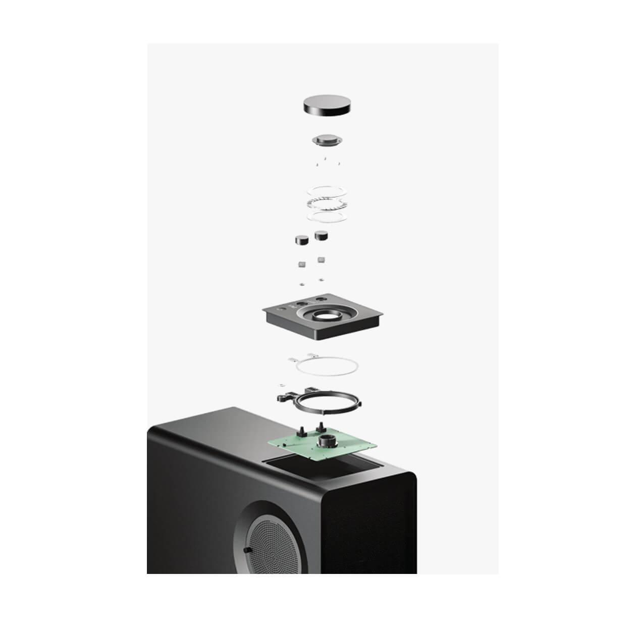
On the Hydration Bottle project, the 3D model was used to calculate internal volumes and check formability, tying the design directly to tooling and assembly reality. The lid mechanism work also used 3D mockups to communicate sealing and moving parts clearly. That is DFM thinking early, not late.
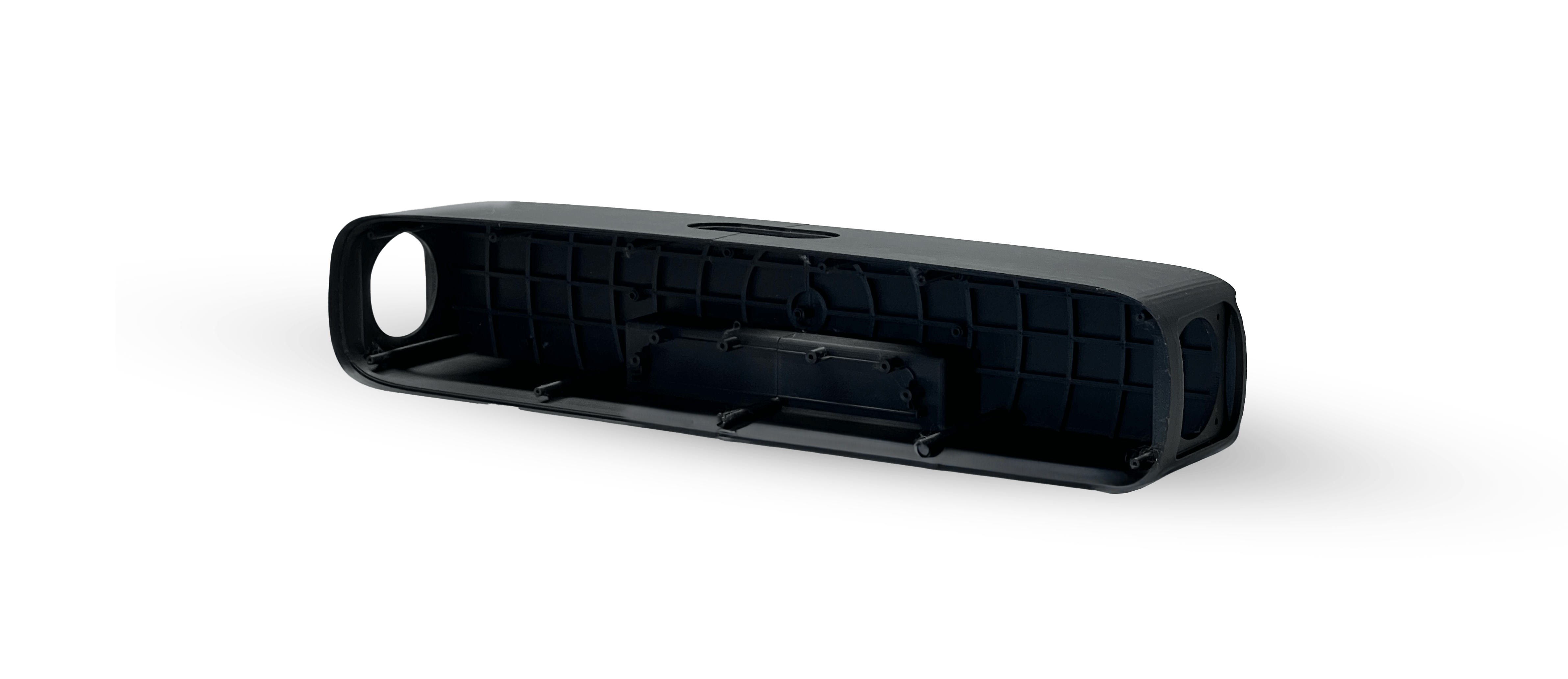
TVTR Compact Soundbar, tool ready intent before handoff
On the TVTR Compact Soundbar project, the brief demanded low cost and a crowded market. The work included working drawings for prototype handoff and initial injection moulding studies so parts were tool ready, plus a 3D printed enclosure for testing. That is a clean example of linking form, cost, and manufacturability early.
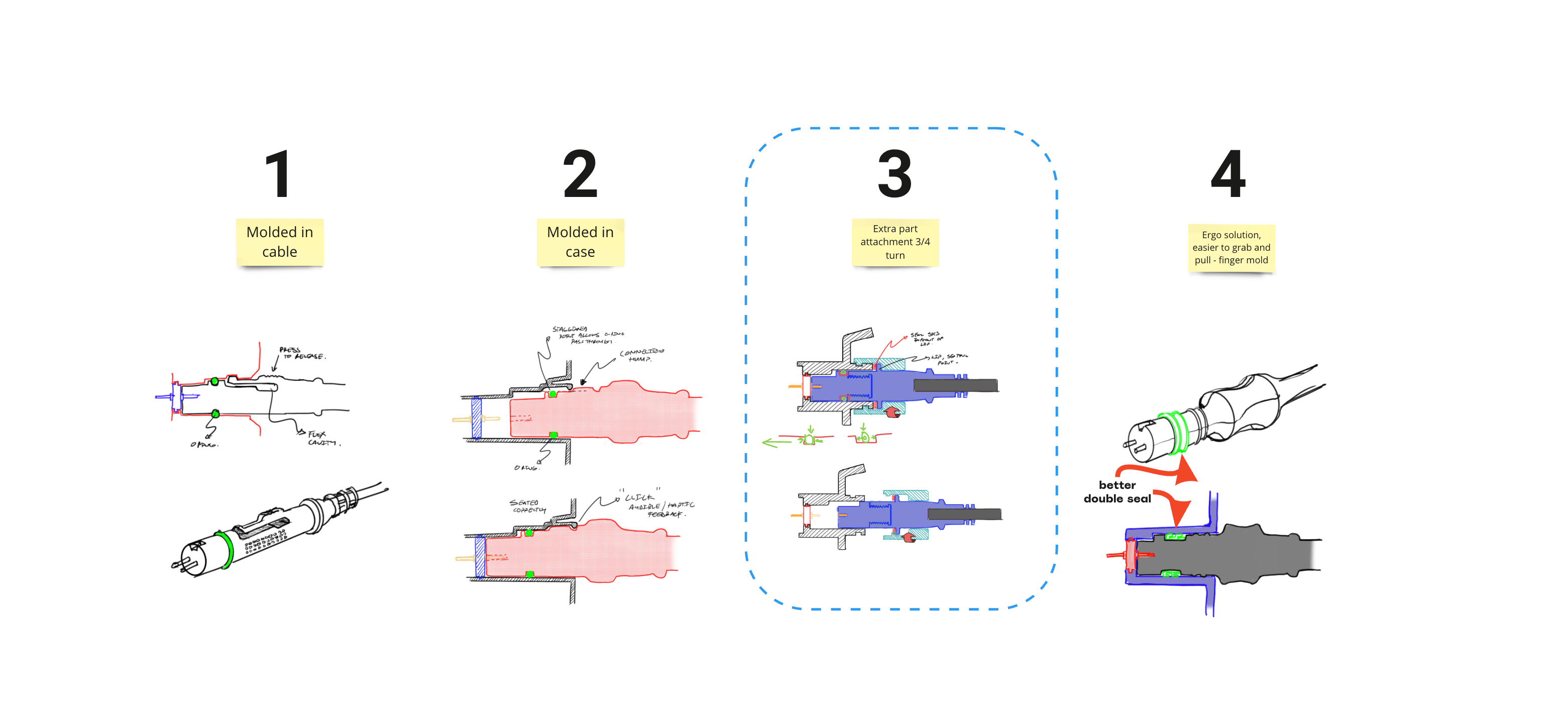
Lowrance Eagle, solving a real failure mode, not just styling
On Lowrance Eagle, user feedback highlighted connector difficulty which created sealing risk, because the device needed to be waterproof. The work moved through root cause and concept development to a twist lock connector solution that simplified insertion and reduced user error, and the concept was strong enough to patent. That is the kind of DFM adjacent thinking that prevents expensive failures later, behaviour, sealing, and manufacturability working together.
Air D1, complexity demands structure
Air D1 is a reminder that DFM is also about systems. When assemblies get complex, the only way through is clean structure, sub assemblies, and disciplined testing. The write up notes intense scrutiny of minor details to ensure a high quality outcome, which is where DFM and perceived quality meet.
Final thought
Good DFM is not about making products boring. It’s about making ambition buildable. It’s the difference between a product that looks great in a deck and a product that ships cleanly, repeatedly, at cost, with quality you can trust. If you want to move fast, be disciplined early. If you want to sleep at night, write the assembly story. If you want fewer surprises, prototype the interfaces that can break you.
How I help teams avoid DFM blowouts
I offer a focused DFM Health Check for teams who are approaching prototyping, supplier quoting, or tooling and want a reality check before they commit. It’s designed to surface problems early, while they are still easy to fix.
Typical outputs:
- DFM preflight review by process, moulding, machining, sheet metal, soft goods
- Assembly story review, tool access, cable routes, seals, fasteners
- Critical tolerance and stackup identification
- A short risk register with recommended prototypes or design changes
- A supplier question pack that gets better answers
If that sounds useful, start with Services and book a call. The goal is not to avoid constraints. The goal is to design with them, and ship something that lasts.
 Book a Call
 Instagram.
 linkedin.